Understanding the Testing Procedures for Directional Couplers
 Grasping the intricacies of testing directional couplers is vital for experts engaged with RF and microwave systems. These elements are crucial for power measurement and signal monitoring, thus their precision and dependability are of utmost importance. This article will guide you through the basic principles, preparations before testing, and different testing techniques related to directional couplers.
Fundamental Concepts of Directional Couplers
What is a Directional Coupler?
A directional coupler is an RF component used to split or combine signals. It couples a specific proportion of the signal power traveling through the input port to a coupled port, while allowing the remainder to pass through the main line largely undisturbed. This enables accurate measurement and monitoring of the signal without significant interference or loss in the primary transmission path.
Functions and Applications
Directional couplers are employed in various functions such as monitoring signal levels, power measurement, and reflection coefficient measurement. They find applications in several fields including telecommunications, radar systems, and signal testing equipment. The capabilities of directional couplers to provide isolated and proportional sampling of the signal make them invaluable in both testing and operational environments.
Importance in Electronic Systems
In RF and microwave systems, the role of a directional coupler is critical for performance verification and troubleshooting. It allows engineers and technicians to measure forward and reflected power accurately, ensuring that the system operates within its desired parameters. This is particularly important for maintaining the integrity and efficiency of high-frequency signal transmissions, thus contributing to the overall reliability and performance of electronic systems.
Pre-Testing Preparations for Directional Couplers
Selecting Appropriate Equipment
Prior to testing a directional coupler, it is crucial to choose the appropriate equipment. This generally involves signal generators, network analyzers, as well as suitable cables and connectors. The chosen equipment must be compatible with the frequency range and power levels of the directional coupler under test. Having high-quality, calibrated instruments is vital for achieving precise and dependable measurements.
Setup Procedures
Proper setup is crucial for accurate testing of directional couplers. Begin by ensuring that all devices are powered off before connections are made.
Connection Checklist
Ensure all cables and connectors are clean and free from damage. Connect the input port of the directional coupler to the signal source and the output port to a load or measuring instrument. Double-check all connections to ensure they are secure and properly seated.
Initial Calibration Steps
Calibrate the test equipment according to the manufacturer’s instructions. This often involves setting the network analyzer to the desired frequency range and performing a thru-calibration to eliminate any system errors. Proper calibration ensures that the measurements taken are accurate and reflective of the component’s performance.
Testing Methods for Directional Couplers
Directivity Testing
Explanation of Directivity
Directivity is a metric that evaluates the efficiency of a directional coupler in isolating the input signal from the output signal. When directivity is high, it means the directional coupler can successfully distinguish between forward and reflected signals. This capability results in more precise measurements of reflected power.
Procedure to Measure Directivity
To measure directivity, connect the coupler’s input to a signal source and the output to a matched load. Measure the power at the coupled port when operating in the forward direction. Then, reverse the roles of input and output, and measure the reverse direction power at the same coupled port. The difference in these measurements represents the directivity of the directional coupler.
Insertion Loss Evaluation
What is Insertion Loss?
Insertion loss is the amount of signal power lost when the signal passes through the directional coupler. It is an important metric indicating the efficiency of the directional coupler in preserving the signal’s power.
Steps to Measure Insertion Loss
Connect the directional coupler between a signal generator and a load. Measure the power level at the output port without the coupler in place; then, insert the coupler and measure the output power again. The difference between these two power levels gives the insertion loss of the directional coupler.
Coupling Factor Measurement
Understanding Coupling Factor
The coupling factor represents the ratio of power transferred from the input port to the coupled port. It measures the amount of the input signal sampled by the coupled port, with common values ranging between 3 and 30 dB.
Measuring Techniques for Coupling Factor
To measure the coupling factor, connect the input port to a signal generator and measure the power at the main line output port and the coupled port. The coupling factor is calculated as the difference in power levels between the input and the coupled port. Accurate coupling factor measurement is vital for ensuring the effectiveness of the directional coupler in signal monitoring applications.
RFecho
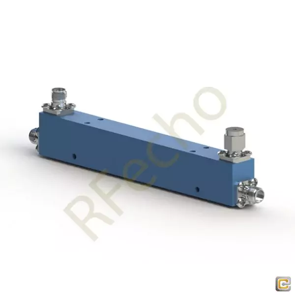
RFecho‘s directional coupler is a crucial component in RF and microwave systems that enables precise power measurement and signal monitoring. This high-performance device is designed to split power between the main transmission line and a coupled port, allowing for simultaneous power measurement and signal analysis.
RFecho’s directional coupler stands out for its exceptional accuracy, reliability, and durability. It is constructed using high-quality materials and advanced manufacturing techniques, ensuring superior performance even in demanding environments. The coupler offers excellent coupling flatness and directivity, resulting in accurate power measurement and minimal signal distortion.
With a wide range of frequency bands, power handling capacities, and coupling ratios available, RFecho’s directional couplers can be tailored to meet specific system requirements. They are suitable for various applications, including telecommunications, aerospace, defense, and research laboratories.
RFecho is dedicated to ensuring customer satisfaction and offers extensive technical support throughout the entire product lifecycle. Their skilled engineering team is always on hand to respond to questions, assist with product selection, and offer post-sales support.
In summary, RFecho’s directional coupler is a reliable and high-performance device that plays a crucial role in power measurement and signal monitoring in RF and microwave systems. With its exceptional accuracy, durability, and customization options, RFecho‘s directional coupler is the ideal choice for professionals seeking precise and reliable power measurement solutions.
In conclusion, understanding the procedures for testing a directional coupler is essential for ensuring its effective performance in RF and microwave systems. By following a structured approach to pre-testing preparations and utilizing accurate testing methods, you can ensure the reliable operation and measurement accuracy of these crucial components.
 Interpreting Test Results
 Interpreting Test Results
Accuracy of Measurements
Interpreting test results for a directional coupler requires a keen understanding of measurement accuracy. High-quality measurements are critical as they determine the legitimacy of the data obtained during testing. Accuracy can be influenced by various factors, including the calibration of the test equipment, the stable operation of signal generators, and even environmental conditions such as temperature and humidity. Ensuring that these variables are controlled and accounted for will allow for the maintenance of high precision in the testing outcomes, thus validating the performance of the directional coupler.
Identifying Potential Issues
Once the accuracy of measurements is confirmed, the next step involves detecting any potential problems with the directional coupler. Issues such as high insertion loss, low directivity, or fluctuations in the coupling factor can indicate faults in either the component or the testing setup. Routine diagnostic checks, comparing test results with previous data, and cross-referencing with manufacturer specifications can aid in identifying inconsistencies and anomalies. Early detection of these issues is crucial for preserving the integrity and reliability of the RF system utilizing the directional coupler.
Best Practices for Testing Directional Couplers
Maintaining a Clean Work Environment
Maintaining a clean and organized work environment is crucial during the testing of a directional coupler. Dust, dirt, and other contaminants can interfere with the performance of the RF equipment and affect the accuracy of the measurements. It is important to regularly clean all test instruments, connectors, and cables to prevent any adverse impacts on the test results. Proper storage of equipment and the use of anti-static materials can further enhance the reliability of the testing process, ensuring that the integrity of the directional coupler is not compromised by external factors.
Regular Calibration of Equipment
Calibration of test equipment is a cornerstone of accurate measurement in directional coupler testing. Instruments should be calibrated regularly according to the manufacturer’s guidelines to ensure their accuracy and functionality. This involves using high-precision calibration standards and procedures that are traceable to national or international standards. Regular calibration helps in detecting any drift or degradation in the performance of the test equipment, which, if left unchecked, could lead to erroneous measurements and faulty interpretations of the directional coupler’s performance.
Recording and Analyzing Data Consistently
Consistent data recording and analysis are vital for meaningful interpretation of the directional coupler test results. Developing a standardized procedure for documenting each test’s parameters, conditions, and outcomes ensures that data is comparable over time and across different units. Utilizing specialized software for data analysis can provide deeper insights into trends, variations, and potential issues. Thorough documentation also facilitates troubleshooting and provides a reliable reference for ongoing evaluations, thereby enhancing the overall understanding and reliability of the directional coupler’s performance.
In summary, possessing a comprehensive grasp of the processes, preparations, and optimal practices in testing a directional coupler is crucial. This expertise guarantees that these essential components operate efficiently within RF and microwave systems, thereby upholding system dependability and performance. By adhering to well-organized pre-testing plans, utilizing precise testing techniques, and following best practices, professionals can secure accurate and dependable measurement results, ensuring the peak functionality of their directional couplers.