From Signal to Success: Using Signal Generators to Optimize Antenna Designs
Exploring the link between signal generators and antenna analysis is crucial in understanding how to maximize signal transmission and reception effectiveness.
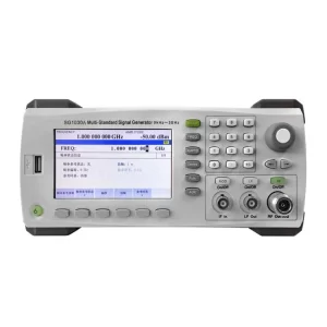
Signal generators are crucial in the process of analyzing antennas as they help engineers to evaluate the performance of an antenna.
Types of Signal Generators
This part will show diverse signal generator types, and highlight their key features.
Signal generators that focus specifically on generating radio frequency signals play a role in the realm of communication systems. These generators are capable of producing an array of frequencies to facilitate testing for a variety of antennas and RF components. Moreover, they offer a selection of modulation options contributing to their versatility as tools for evaluating communication standards.
Vector Signal Generators
Vector signal generators belong to a category of signal generators that excel in producing intricate digitally modulated signals with great precision and accuracy. They are widely used in testing communication systems that depend on modulation techniques. Vector signal generators provide compatibility with communication protocols and the ability to adjust to upcoming technologies.
Setting Up Your Signal Generator for Antenna Characterization
Antenna characterization is the process of evaluating and quantifying an antenna’s performance.
Choosing the Right Signal Generator
They produce precisely controlled electromagnetic waves, acting as controlled signal sources for testing. By transmitting known signals with specific frequencies, amplitudes, and modulations, signal generators allow for precise measurement of crucial antenna parameters.
Frequency Range Considerations
When choosing a signal generator make sure it can cover all the frequencies the antenna is designed to work with to accurately assess its performance across the spectrum intended for use.
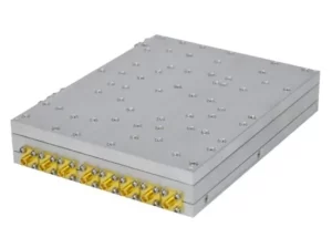
The signal generator needs to be able to produce the waveform types for the antenna testing procedures needed. Typical waveform options include sine waves shaped pulses and triangular patterns. For tests, there are arbitrary waveform generators (AWGs) that enable users to design custom waveforms tailored to specific testing needs.
Output Power Considerations
The power output from the signal generator needs to be strong enough to ensure there is a signal at the receiving end of the antenna testing arrangement. Having power can cause signal distortion or harm delicate parts whereas not enough power could lead to weak signals that are hard to measure precisely.
Modulation Capability Considerations
To ensure that antennas designed for communication systems work effectively during testing procedures suitable modulation features should be provided by the signal generator. This involves adjusting properties of the signal, like frequency or amplitude to data. The specific type of modulation employed in the communication setup dictates the modulation capabilities of the signal generator.
Essential Accessories
To optimize the performance and fully utilize your signal generator it’s essential to select the accessories.
- High-quality cables and connectorsare critical for maintaining signal integrity and minimizing signal loss or distortion. Choose cables with appropriate impedance and shielding properties to match your signal generator’s specifications. Also, ensure that connectors are compatible and provide a secure connection.
- Attenuatorsreduce the signal amplitude without altering other characteristics, such as frequency or waveform shape. They help protect sensitive devices under test from excessive signal levels and prevent distortion or damage.
- An oscilloscopeis indispensable for visualizing and analyzing the signals generated by your signal generator. It allows you to verify the waveform shape, frequency, amplitude, and other parameters, ensuring that the generated signals meet your project requirements.
- A frequency countermeasures the frequency of the generated signals with high accuracy. It helps verify that the signal generator operates within the specified tolerances and provides additional confidence in your measurements.
- A stable and reliable power supplyis essential for maintaining consistent performance from your signal generator. Ensure your power supply can deliver the required voltage and current levels without introducing unwanted noise or fluctuations.
Having all these add-ons is crucial for making sure your signal generator is running smoothly and effectively as a system setup. These accessories play a role in guaranteeing trustworthy results during testing and measuring procedures.
Performing Antenna Characterization Measurements
Measuring Radiation Pattern
The way an antenna emits power in three spaces is shown by its radiation pattern. It helps in understanding how focused the antenna is and the width of the beam it produces. There are also factors, like sidelobe levels that are used to assess how well it performs.
Setting Up the Measurement System
In order to assess the radiation pattern of an antenna accurately in a controlled setting, like a chamber that reduces signal reflections to a minimum; position the antenna under examination as instructed. Connect it to a signal generator that emits a continuous wave signal at the specific frequency needed for testing purposes. A receiving antenna fixed on a rotating platform captures the emitted signals from angles while measuring the strength of each signal received at points. These measurements are then. Depicted graphically by plotting the received signal strengths against their angles to create a visual representation of how the antenna’s radiation pattern looks in practical terms.
Interpreting Radiation Pattern Results
Studying the radiation pattern gives us insights into how the antenna is working. The main lobe shows where the signal is strongest and points towards where the antenna is sending or receiving signals. The beamwidth measures how wide the main lobe spreads out and gives us an idea of how much area the antenna covers. The sidelobes are lobes around the one that show radiation going in directions we don’t want.
Measuring Antenna Gain
The antenna gain measures how well the antenna can concentrate emitted power in a direction when compared to an antenna, like an isotropic radiator that distributes power evenly in all directions.
Measurement Techniques
When determining gain measurements in antennas we compare the signal strength received by the antenna being tested to that of a reference antenna both exposed to the signal source. The disparity in received power measured in decibels (dB) indicates the gain of the antenna under examination.
Measuring Directivity
Directivity is closely linked to gain as it indicates the ratio of an antenna’s peak radiation intensity to its radiation intensity across all directions; unlike gain which considers losses in the antenna system overall directivity specifically looks at how the antenna can focus radiated power.
Calculating Directivity from Radiation Pattern
Analyzing the antenna’s radiation pattern allows for the determination of directivity by integrating the power density across all angles and comparing it to the maximum power density value.
Measuring Antenna Impedance
The impedance of the antenna refers to the resistance that the signal faces at the input terminals of the antenna system. It’s important to have a match in impedance between the antenna and the transmission line to ensure power transfer. If there are mismatches in impedance it can cause reflections and power loss which would affect the performance of the antenna system adversely.
Measurement Methods
Typically in antenna testing procedures a device known as a vector network analyzer (or VNA) is used. The VNA sends out a signal that varies in frequency to the antenna and then measures the signal that bounces back. By studying how the incoming and reflected signals relate to each other the impedance of the antenna can be figured out based on the frequency at which it operates.
Advanced Techniques in Antenna Characterization
Modulation Techniques
Signal generators that have the ability to modulate signals enable engineers to evaluate antennas by simulating real-world communication scenarios with modulation techniques, like amplitude modulation (AM) frequency modulation (FM), or phase modulation (PM). This helps in assessing how the antenna functions in conditions to its actual usage environment.
Frequency Sweeping
Sweeping frequencies entails adjusting the signal generator’s output frequency within a specified range to allow engineers to examine how the antenna reacts across frequencies on the spectrum effectively revealing frequencies and any potential impedance mismatches that could impact the antenna’s performance within its operational frequency range.
RFecho: Your Trusted Signal Generator Partner
RFecho provides a range of signal-generation products. Serves as a supplier for RF and microwave components in the industry.
RFecho’s Signal Generation Solutions
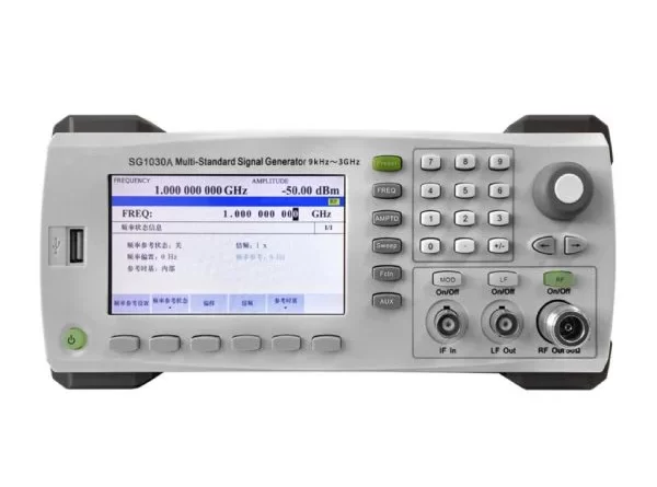
The MSG150A Modular Microwave Signal Generator from RFecho offers a range spanning from 100 kHz to 15 GHz. RFecho also provides RF signal generators that cater to wave modulation and pulse modulation along with AM/FM/FМ analog modulation solutions. Moreover, the SG821 signal generator by RFecho comes with LAN and USB interfaces. Is compatible with the SCPI command for aiding in development during production.
Analyzing and Interpreting Measurement Results
When you gain measurement results, accurate analyzing and interpreting are crucial.
Data Analysis and Visualization
Analysis of antenna features results in an amount of data that requires effective tools for interpretation and display purposes. Typically there are software tools that can handle the data captured during measurements and present it in visuals like graphs or 3D representations. These visual aids help in grasping the antenna’s behavior with regard to its radiation pattern, gain, directivity, and impedance among other factors.
Identifying Potential Issues
When engineers study the measurement results they can spot issues that might be impacting how well the antenna works. If the radiation pattern doesn’t match up as predicted it could mean there are problems with how the antenna was designed or made. By finding and fixing impedance mismatches using matching networks or making changes to the antenna structure engineers can improve its performance. The analysis provides insights that help in making design enhancements over time and creating antennas that meet performance requirements effectively.
Conclusion
Signal generators play a role in evaluating antennas by delivering signals to accurately gauge their performance levels. This allows engineers to measure factors like radiation pattern, gain, directivity, and impedance. This comprehensive assessment provides insights into the antenna’s strengths and weaknesses. Engineers can fine-tune antenna designs effectively by selecting signal generators and accessories following measurement methods and interpreting the data obtained from tests. These iterative improvements ultimately lead to customized solutions for communication needs.

