The Formula for a Low-Pass Filter A Comprehensive Guide
Introduction to Low-Pass Filters
A low-pass filter is an essential element in multiple domains of electronics and signal processing. This type of filter permits signals with a frequency below a designated cutoff frequency to pass, while it diminishes frequencies above this cutoff point. Mastering the low-pass filter formula is crucial for the design and enhancement of electronic circuits tailored for specific purposes. Be it in audio engineering, telecommunications, or radio-frequency circuits, the low-pass filter is indispensable for shaping and managing signal characteristics.
What is a Low-Pass Filter?
A low-pass filter is a type of electronic filter that passes signals with a frequency lower than a chosen cutoff frequency and attenuates signals with frequencies higher than the cutoff. The main function is to reduce high-frequency noise or to smoothen a signal. This feature is invaluable in audio electronics, where it helps in eliminating unwanted high-frequency noise, or in digital signal processing, where it serves to extract essential signals from raw data.
Applications and Importance in Electronics
Low-pass filters are essential in numerous electronic applications. In audio processing, they help in reducing unwanted high-frequency components to deliver clean sound. In the realm of telecommunications, these filters are integral in modulating and demodulating signals. Additionally, in control systems, low-pass filters are used to ensure stable system responses by filtering out rapid fluctuations. Overall, the low-pass filter’s role in refining and managing signal content makes it indispensable in modern technology.
Basic Concepts and Terminology
Understanding a low-pass filter involves grasping several fundamental concepts and terminologies. The cutoff frequency refers to the frequency at which the filter begins to attenuate the signal. Attenuation is the reduction in signal strength. The passband is the range of frequencies that are allowed to pass through, while the stopband includes frequencies that are significantly attenuated. Lastly, the slope of the filter reflects how sharply it transitions from passband to stopband.
With a specialization in frequencies ranging from low frequencies up to THz frequencies, RFecho offers a wide range of innovative solutions to meet the diverse needs of its customers.
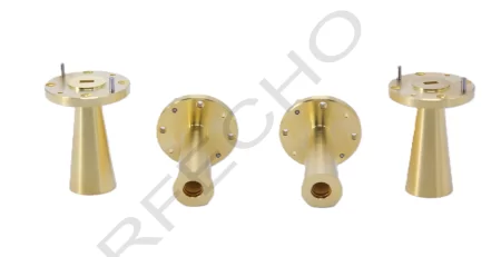
RFecho’s expertise lies in the design of various types of antennas, including standard gain horns, reflector antennas, CATR feeds, antenna arrays, corrugated horns, ridged horns, near field probes, planar antennas, and microwave frequency band antennas. Their capabilities also extend to the design of orthogonal mode couplers, polarizers, rotary joints, polarization duplexers, duplexers, angle trackers, and custom solutions. This comprehensive range of antenna designs ensures that RFecho can cater to a wide range of applications in fields such as remote control, telemetry, electronic countermeasures, electronic reconnaissance, data communications, satellite positioning, and radar.
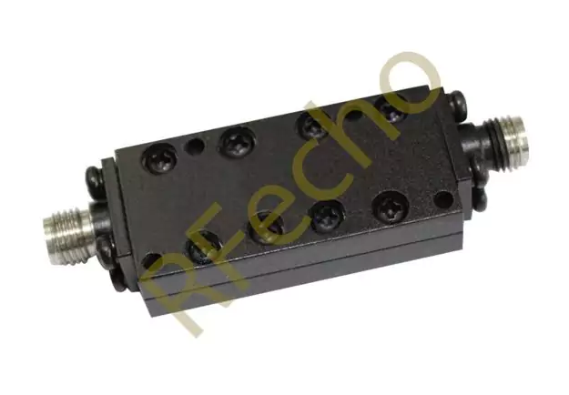
In addition to their antenna expertise, RFecho offers a diverse range of passive and active products. Their passive products include various frequency bands, filters, power dividers, couplers, wave conversion components, load components, and waveguide components. On the other hand, their active products consist of low noise amplifiers, power amplifiers, phase shifters, and more. RFecho excels in designing products with high power, high integration, high difficulty, and special requirements, making them a preferred choice for customers with unique needs.
The Formula for a Low-Pass Filter
Mathematical Representation
The mathematical representation of the formula for a low-pass filter delineates the relationship between its various components. The transfer function of a basic RC (resistor-capacitor) low pass filter is expressed by:.
[ H(f) = \frac{1}{1 + j \frac{f}{f_c}} ]
where ( H(f) ) is the transfer function, ( f ) is the frequency, ( f_c ) is the cutoff frequency, and ( j ) is the imaginary unit. This equation helps in understanding how the filter affects different frequency components of the input signal.
Components and Variables Explained
Understanding the formula involves a deep dive into its components and variables:
Capacitors
In a low-pass filter, capacitors are crucial in shaping the filter’s characteristics. The capacitor’s value dictates the circuit’s response speed to fluctuations in signal frequency. By storing and releasing electrical energy, capacitors affect the handling of signals at different frequencies.
Resistors
Resistors, paired with capacitors, set the cutoff frequency of the low pass filter. A resistor’s value, in conjunction with the capacitor, defines the rate at which the output signal drops off as frequency increases. The resistor acts as a moderating component that controls the flow of electrical current.
Cutoff Frequency
The cutoff frequency ( f_c ) is a crucial variable in the low pass filter formula. It is defined by the values of the resistor (( R )) and the capacitor (( C )) in the circuit and is given by the formula:
[ f_c = \frac{1}{2 \pi R C} ]
This equation demonstrates that by choosing suitable values for the resistor and capacitor, a filter with the desired cutoff frequency can be designed.
Derivation of the Low-Pass Filter Formula
Step-by-Step Derivation Process
Deriving the low pass filter formula involves a systematic approach. Starting with Kirchhoff’s Voltage Law (KVL) in a simple RC circuit, the voltage across the resistor (V_R) and the capacitor (V_C) must add up to the input voltage (V_in):
[ V_{in} = V_R + V_C ]
Given ( V_R = IR ) and ( V_C = \frac{Q}{C} ), and using Ohm’s Law (( V = IR )) for AC circuits, we rewrite ( V_C ) in terms of current and impedance. The impedance of a capacitor in an AC circuit is ( Z_C = \frac{1}{j \omega C} ). Thus, the transfer function ( H(f) ) is derived by applying these relationships and considering the steady-state behavior of the circuit.
Understanding Transfer Functions
Transfer functions offer a concise method to represent the input-output relationship of a filter in the frequency domain. For a low pass filter, it illustrates how various frequency components of the input signal are diminished.
Laplace Transform in Filtering
The Laplace Transform is a mathematical tool used to analyze linear time-invariant systems. Applying the Laplace Transform to the circuit equations simplifies solving complex differential equations. For a low-pass filter, the Laplace Transform converts time-domain circuit behavior into the frequency domain, providing insights into how the filter responds to various frequencies.
Impedance in AC Circuits
In AC circuits, impedance extends the concept of resistance to account for both resistive and reactive components. The impedance of capacitors and inductors varies with frequency, which is a crucial factor in filter design. Understanding impedance helps in predicting how the circuit will filter different frequency components, thus enabling accurate design of low pass filters.
This comprehensive guide provides a foundational understanding of the formula for a low pass filter, touching on its mathematical representation, essential components, and the derivation process. By understanding these core elements, one can design effective filters for various electronic applications.

Practical Applications of the Low-Pass Filter Formula
Audio Signal Processing
One significant application of low pass filters is in audio signal processing. By eliminating high-frequency noise, audio engineers can improve the quality of sound recordings. For example, a low pass filter can be employed to reduce unwanted high-frequency hiss in a recorded track, thereby maintaining clarity and fidelity. Additionally, in the process of audio mixing, these filters assist in blending various tracks seamlessly by restricting high-frequency sounds that could otherwise conflict. This method is crucial for producing a refined final mix that is enjoyable for listeners. Moreover, low-pass filters are incorporated into equalizers to manage the tonal balance within audio systems, enabling customized sound experiences.
Image Denoising and Smoothing
In the realm of image processing, low pass filters are instrumental in denoising and smoothing images. By attenuating high-frequency components, which often correspond to noise, these filters help in creating clearer and more aesthetically pleasing images. For example, in medical imaging, a low pass filter can remove grainy noise from an X-ray or MRI scan, aiding in better diagnosis. Photographers also use these filters in post-processing to remove sensor noise from digital photos, ensuring higher image quality. Additionally, in computer vision, low-pass filters are used in pre-processing steps to enhance the performance of algorithms used for object detection and recognition.
Telecommunications Systems
Low pass filters are crucial in telecommunications systems for modulating and demodulating signals. In communication channels, these filters help in reducing unwanted frequencies and noise, thereby ensuring a clearer transmission of information. For instance, in radio communications, a low pass filter is used to filter out high-frequency interference from the received signal, ensuring that the essential information is accurately captured. They are also used in data transmission over cables, where they filter out high-frequency noise that could corrupt the transmitted data. Additionally, low-pass filters play a significant role in wireless communication technologies, ensuring the smooth transmission and reception of signals over various frequencies.
Testing and Implementing Low-Pass Filters
Simulation Software and Tools
In modern electronic design, testing low-pass filters before physical implementation is essential. Various simulation software and tools are available to achieve this.
MATLAB/Simulink
MATLAB/Simulink is a widely used tool for simulating low-pass filters. With its powerful computational abilities, MATLAB can model complex filter designs and analyze their frequency response. Engineers use it to simulate different scenarios, optimize filter parameters, and predict the performance of the low-pass filter in real-world applications. Simulink, an extension of MATLAB, provides a graphical interface and block diagram environment where users can simulate dynamic system behavior, making it easier to visualize how the filter interacts with other components in a system.
PSPICE
PSPICE is another vital tool for simulating low-pass filters. It allows engineers to perform circuit simulations to verify the design and functionality of the filters. PSPICE offers detailed analysis features such as time-domain and frequency-domain simulations, enabling the designers to understand the filter’s behavior under various conditions. Designers can also use it to troubleshoot and refine their low pass filter designs before physical prototyping, reducing the risk of errors and saving valuable development time.
Real-World Implementation Techniques
Implementing low-pass filters in real-world circuits requires careful consideration and precise techniques to ensure the desired performance.
In practice, discrete components like resistors and capacitors are used to construct RC low-pass filters. Attention to component tolerance and stability is paramount, as slight variations can affect the cutoff frequency and overall filter performance. Additionally, designers often use printed circuit boards (PCBs) with meticulous layout designs to minimize parasitic inductance and capacitance, which can alter the filter characteristics. Shielding and grounding techniques are also employed to protect the circuit from external noise and interference.
For more intricate applications, active low-pass filters are employed, utilizing operational amplifiers in conjunction with resistors and capacitors. These active filters provide benefits like gain control and enhanced performance across a broader frequency spectrum. Furthermore, digital low-pass filters are gaining popularity, using digital signal processing methods to attain precise and flexible filtering without the necessity for bulky components.
Final Thoughts on Understanding the Low-Pass Filter Formula
Understanding the low pass filter formula is fundamental for anyone involved in electronics and signal processing. From its mathematical representation, comprising resistors and capacitors, to the various practical applications across different fields, this filter remains a cornerstone of modern electronic circuits. Whether for audio enhancement, image processing, or telecommunications, the mastery of low-pass filter design and implementation ensures improved signal quality and system performance. As technology advances, the ability to efficiently simulate, test, and implement these filters will continue to be essential, solidifying the low pass filter’s role in future innovations.
RFecho has established strong partnerships with renowned institutions and companies worldwide, including Cambridge University, Oxford University, Harvard University, Tsinghua University, Peking University, Facebook, Google, and the China Metrology Institute. These collaborations highlight RFecho’s outstanding innovation capabilities and position them as a key partner in the industry. With a dedicated and experienced team, RFecho has also become a prominent distributor for many global RF companies.
In conclusion, RFecho is the go-to solution for high-performance antenna design and development. Their extensive range of antenna designs, coupled with their expertise in passive and active products, sets them apart in the industry. Choose RFecho for innovative solutions, exceptional service, and the power to enhance your communication and technology capabilities. Don’t forget to explore their high-quality Bias Tee for reliable and efficient signal transmission.